Practical Journal — 8051 Microcontroller experiments using Keil µVision5 and Proteus Simulation
This code is written for an 8051 microcontroller to control a 16×2 LCD display using the 8-bit interface method. The microcontroller displays the text "JAYESH" on the screen via commands and data instructions.
Ports and Pins:
rs (Register Select), rw (Read/Write), and en (Enable) are control pins on P1. Port P2 (data lines D0–D7) sends 8-bit data/commands to the LCD.
Key Functions:
lcdcmd() — Sends a command byte (rs=0, rw=0, en pulse).
lcddata() — Sends a character (rs=1, rw=0, en pulse).
delay() — Simple for-loop delay for LCD processing time.
LCD Commands:
0x38 — 8-bit mode, 5×7 matrix | 0x01 — Clear screen | 0x10 — Cursor blink | 0x0C — Display ON | 0x81 — Cursor line 1, pos 1
Keil µVision5
Proteus 8.13 SP0
#include<reg51.h>

sbit rs= P1^0;
sbit rw= P1^1;
sbit en= P1^2;

void lcdcmd(unsigned char);
void lcddata(unsigned char);
void delay();

void main()
{
    P2=0x00;         // output declaration

    while(1)
    {
        lcdcmd(0x38);   // 5x7 matrix
        delay();
        lcdcmd(0x01);   // clear screen
        delay();
        lcdcmd(0x10);   // cursor blinking
        delay();
        lcdcmd(0x0c);   // display on
        delay();
        lcdcmd(0x81);   // cursor 1st line 1st pos
        delay();

        lcddata('J');
        delay();
        lcddata('A');
        delay();
        lcddata('Y');
        delay();
        lcddata('E');
        delay();
        lcddata('S');
        delay();
        lcddata('H');
        delay();
    }
}

void lcdcmd(unsigned char val)
{
    P2=val;
    rs=0;
    rw=0;
    en=1;
    delay();
    en=0;
}

void lcddata(unsigned char val)
{
    P2= val;
    rs= 1;
    rw=0;
    en= 1;
    delay();
    en=0;
}

void delay()
{
    unsigned int i;
    for(i=0; i<12000; i++);
}
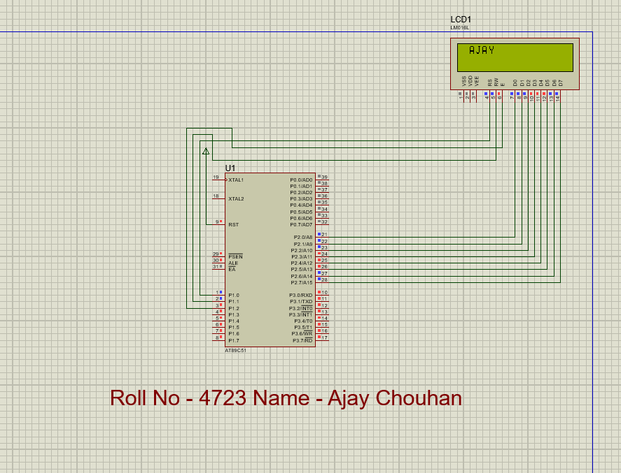
This program demonstrates interfacing an 8051 microcontroller with a 16×2 LCD using basic commands to display "JAYESH". The program initializes the LCD, clears the screen, enables the cursor, and continuously displays the text.
Controls two sets of traffic lights (red, yellow, green) using Port 1. The lights cycle through standard sequences with timing delays.
Pins:
r1, y1, g1 — Set 1 (P1.0–P1.2) | r2, y2, g2 — Set 2 (P1.3–P1.5)
Sequence:
Both red → Set 2 green → Set 1 yellow → Set 1 green (Set 2 red) → Repeat. Delay uses nested for-loops (60,000 iterations).
Keil µVision5
Proteus 8.13 SP0
#include<reg51.h>

sbit r1=P1^0;
sbit y1=P1^1;
sbit g1=P1^2;
sbit r2=P1^3;
sbit y2=P1^4;
sbit g2=P1^5;

void main()
{
    unsigned int i;
    r1=y1=g1=0;
    r2=y2=g2=0;

    while(1)
    {
        r1=1; r2=1;
        y1=0; g1=0; y2=0; g2=0;
        for(i=0;i<60000;i++);
        for(i=0;i<60000;i++);

        g2=1; r2=0;
        for(i=0;i<60000;i++);
        for(i=0;i<60000;i++);

        r1=0; y1=1;
        for(i=0;i<60000;i++);

        g1=1; y1=0; r1=0;
        r2=1; g2=0; y2=0;
        for(i=0;i<60000;i++);

        r1=1; r2=0;
        y1=0; y2=0;
        g1=0; g2=1;
    }
}
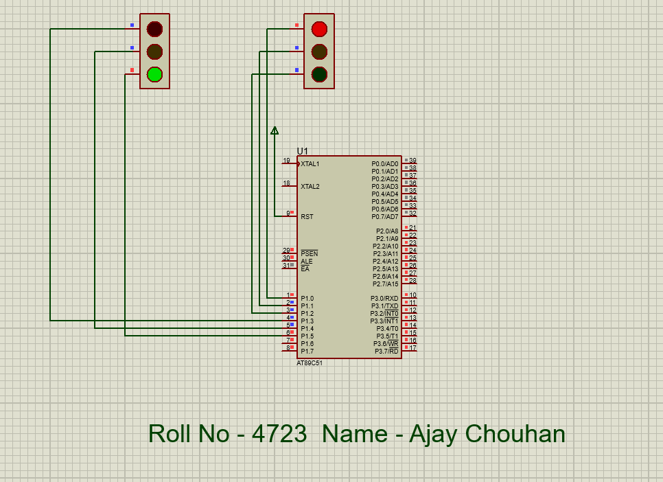
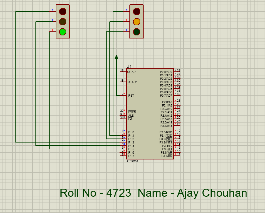
This program simulates a traffic light system using the 8051. It controls two sets of lights cycling through red, yellow, and green phases with timed delays.
A 4×3 keypad is interfaced via Port 1 using row-column scanning. Each row is set low; columns are checked. The matching 7-segment hex code is sent to Port 2.
Keypad → 7-Segment Mapping:
0xF9→1 | 0x99→2 | 0xB8→3 | 0xA4→4 | 0x92→5 | 0x80→6 | 0xB0→7 | 0x82→8 | 0x98→9 | 0xC0→0
Keil µVision5
Proteus 8.13 SP0
#include<reg51.h>

sbit R0 = P1^0;
sbit R1 = P1^1;
sbit R2 = P1^2;
sbit R3 = P1^3;
sbit C0 = P1^4;
sbit C1 = P1^5;
sbit C2 = P1^6;

void seg(unsigned int);

void main()
{
    R0=R1=R2=R3=1; R0=0;
    if(C0==0) seg(0xF9);    // 1

    R0=R1=R2=R3=1; R0=0;
    if(C1==0) seg(0xA4);    // 4

    R0=R1=R2=R3=1; R0=0;
    if(C2==0) seg(0xB0);    // 7

    R0=R1=R2=R3=1; R1=0;
    if(C0==0) seg(0x99);    // 2

    R0=R1=R2=R3=1; R1=0;
    if(C1==0) seg(0x92);    // 5

    R0=R1=R2=R3=1; R1=0;
    if(C2==0) seg(0x82);    // 8

    R0=R1=R2=R3=1; R2=0;
    if(C0==0) seg(0xB8);    // 3

    R0=R1=R2=R3=1; R2=0;
    if(C1==0) seg(0x80);    // 6

    R0=R1=R2=R3=1; R2=0;
    if(C2==0) seg(0x98);    // 9

    R0=R1=R2=R3=1; R3=0;
    if(C1==0) seg(0xC0);    // 0
}

void seg(unsigned int ch)
{
    P2 = 0x00;
    P2 = ch;
}
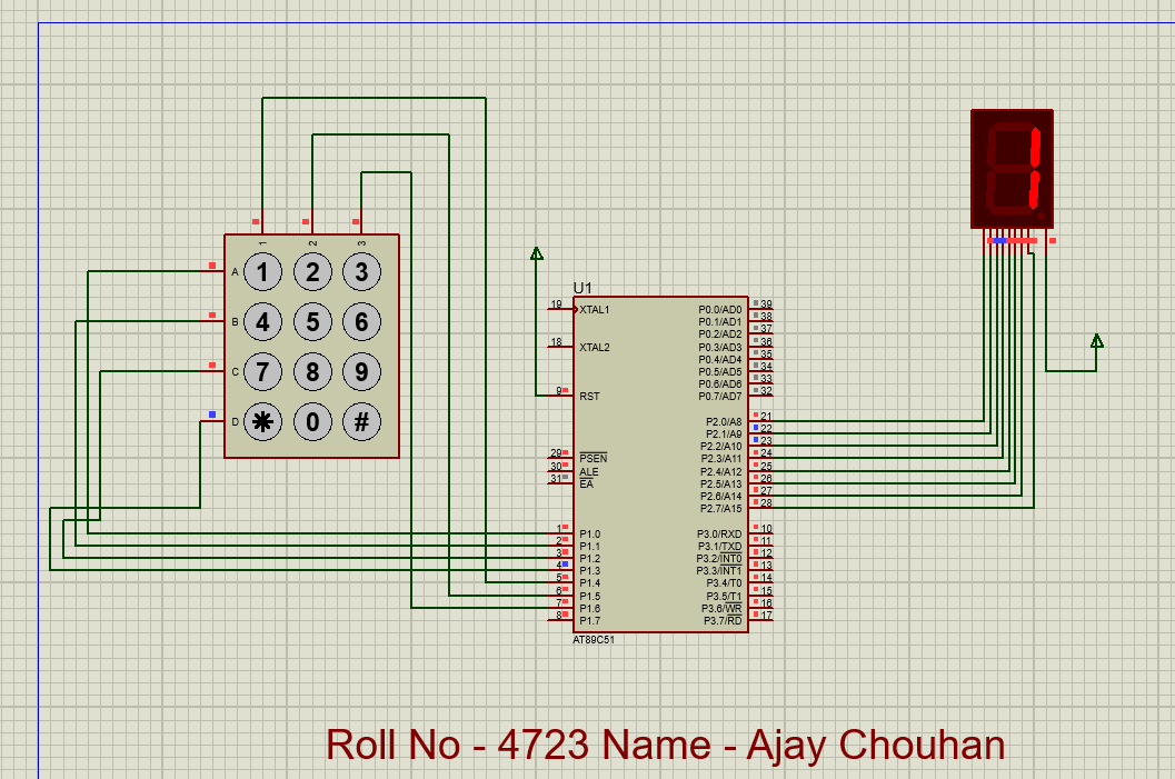
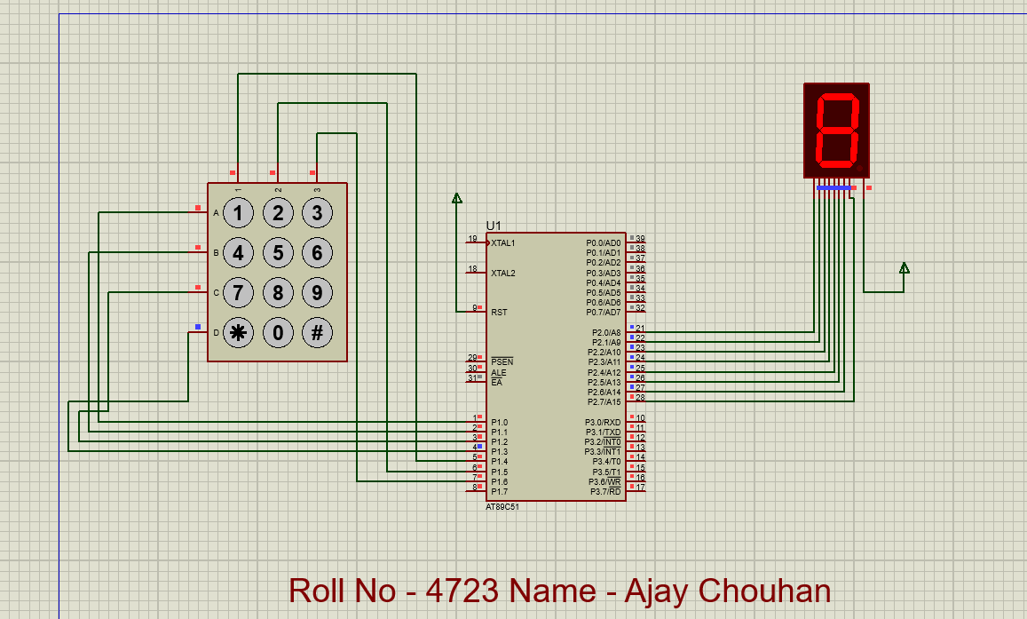
Demonstrates interfacing a 4×3 keypad with the 8051 to display digits on a 7-segment display using row-column scanning and hex-encoded segment values.
A DC motor on P2.0 is driven via an L293D motor driver. Three switches on Port 3 select speed by varying the PWM duty cycle.
Duty Cycle = T_on / (T_on + T_off) × 100%
Low — ON:10, OFF:90 (≈10%) | Average — ON:50, OFF:50 (≈50%) | High — ON:90, OFF:10 (≈90%)
Keil µVision5
Proteus 8.13 SP0
#include<reg51.h>

sbit mot = P2^0;
sbit low = P3^0;
sbit avg = P3^1;
sbit high = P3^2;

void delay(unsigned int);

void main()
{
    mot = 0;
    while(1)
    {
        if(low == 0)        // ~10% duty cycle
        {
            mot=1; delay(10);
            mot=0; delay(90);
        }
        if(avg == 0)        // ~50% duty cycle
        {
            mot=1; delay(50);
            mot=0; delay(50);
        }
        if(high == 0)       // ~90% duty cycle
        {
            mot=1; delay(90);
            mot=0; delay(10);
        }
    }
}

void delay(unsigned int d1)
{
    unsigned int d2;
    for(d2=0; d2<d1; d2++);
}
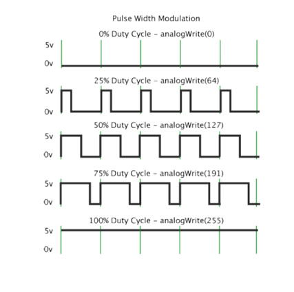
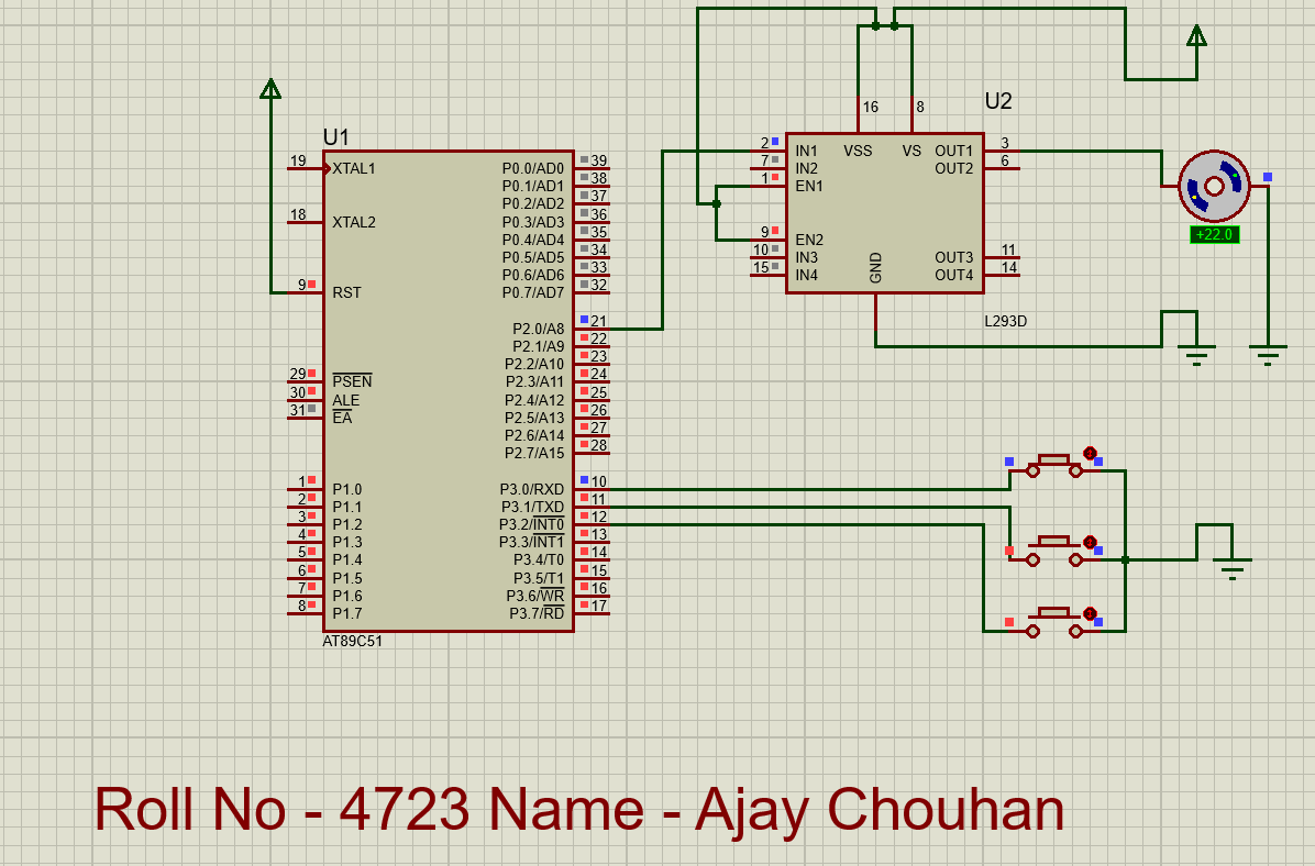
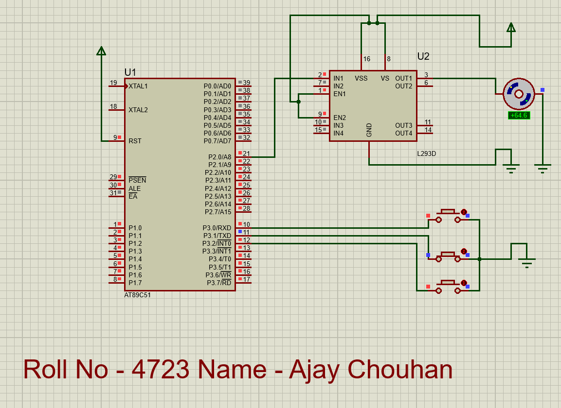
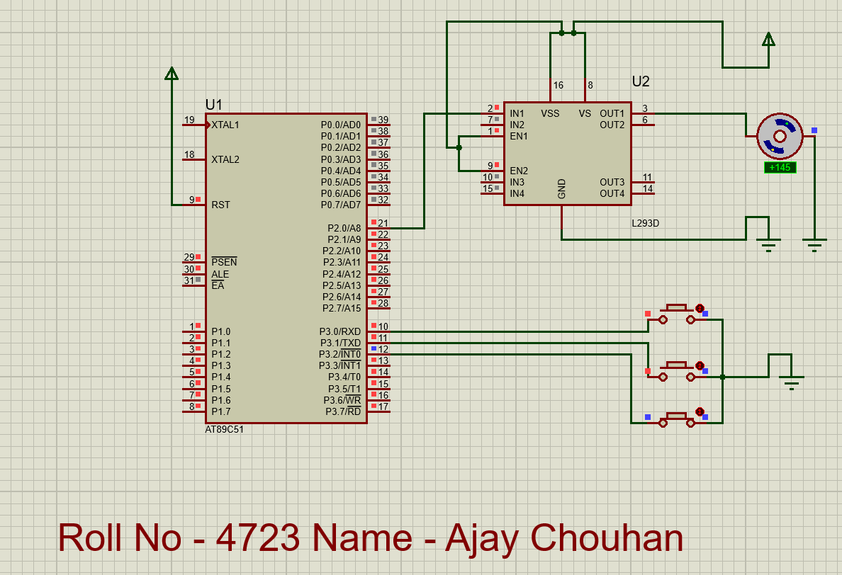
Demonstrates PWM-based DC motor speed control. Three switches select low (~10%), average (~50%), and high (~90%) duty cycles to vary motor speed.
Configures the 8051 UART and continuously transmits 'M'.
Registers:
SCON=0x50 — Mode 1, receiver enabled | TMOD=0x20 — Timer 1 Mode 2 (auto-reload) | TH1=-3 (0xFD) → 9600 baud
Baud Rate:
Timer Rate = 11.0592 MHz ÷ 12 = 921,600 Hz → Baud = (2×921,600) ÷ (32×3) = 9600
#include<reg51.h>

void main()
{
    SCON = 0x50;     // Mode 1, 8-bit UART, REN enabled
    TMOD = 0x20;     // Timer 1, Mode 2 (auto-reload)
    TH1  = -3;       // 9600 baud at 11.0592 MHz
    TR1  = 1;        // Start Timer 1

    while(1)
    {
        SBUF = 'M';          // Transmit 'M'
        while(TI == 0);      // Wait for completion
        TI = 0;              // Clear flag
    }
}
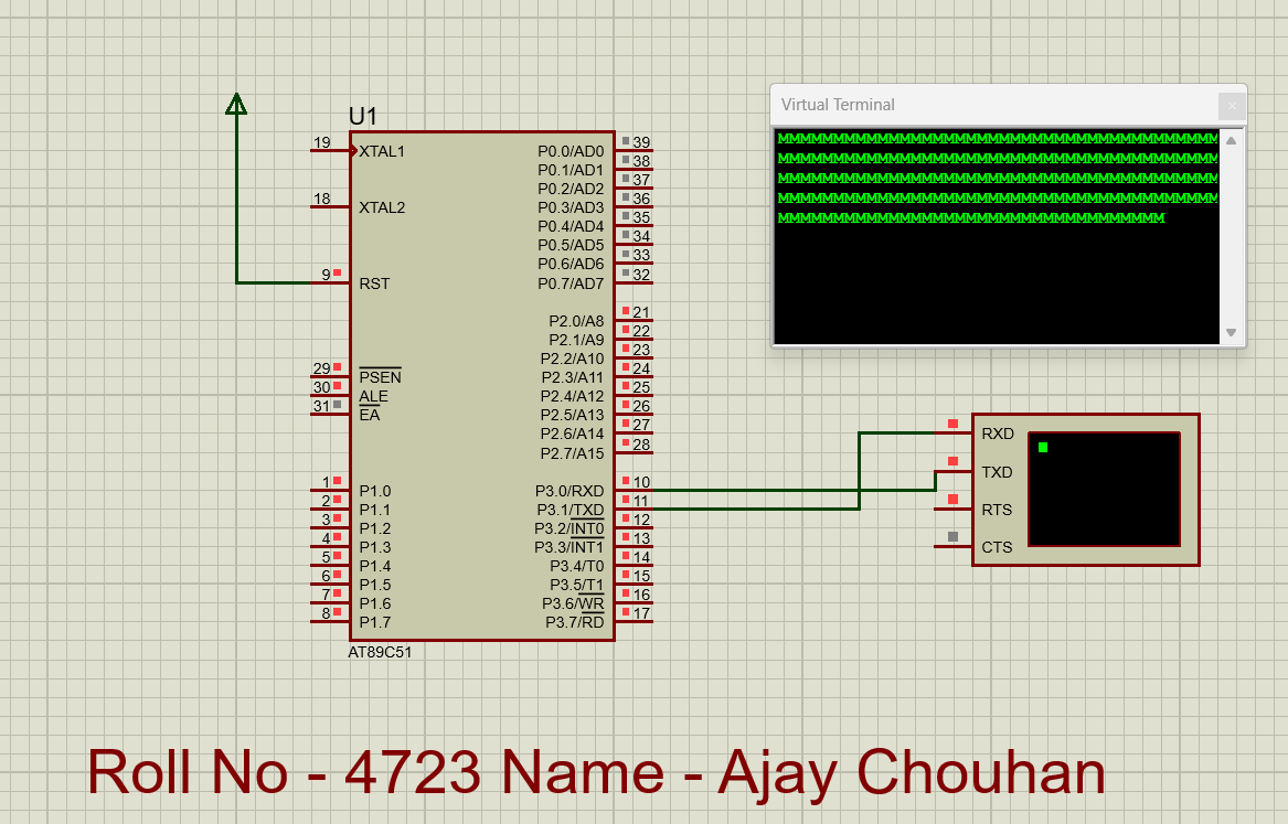
Demonstrates UART serial communication at 9600 baud using Timer 1 auto-reload mode. Character 'M' is continuously transmitted via SBUF.
Port 1 and Port 2 toggle between 0xAA (10101010) and 0x55 (01010101), creating alternating LED blink patterns.
0xAA — Even pins ON | 0x55 — Odd pins ON. Patterns alternate with delay(500).
#include<reg51.h>

void delay(unsigned int time)
{
    unsigned int i, j;
    for(j=0; j<time; j++)
    {
        for(i=0; i<1275; i++);
    }
}

void main()
{
    while(1)
    {
        P1 = 0xAA;       // 10101010
        P2 = 0xAA;
        delay(500);

        P1 = 0x55;       // 01010101
        P2 = 0x55;
        delay(500);
    }
}
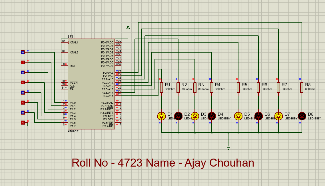
Demonstrates port manipulation and timed output patterns. Ports toggle between 0xAA and 0x55, creating alternating LED effects useful for visual indicators.
Controls a stepper motor elevator. Buttons on Port 0 select floors (0–5). Motor steps via Port 3. Current floor shown on Port 2 → 7447 decoder → 7-segment display.
Functions:
up(b) — Move up b floors (P3: 1→2→4→8→16) | down(b) — Move down (reverse) | control(a) — Calculate diff and call up/down
Input Mapping:
P0=1→Floor 0 | P0=2→Floor 1 | P0=4→Floor 2 | P0=8→Floor 3 | P0=16→Floor 4 | P0=32→Floor 5
Keil µVision5
Proteus 8.13 SP0
#include<REG51.H>
#include<stdio.h>

int p, q, r;
q = 10;       // motor freezing count
r = 10;       // rotation speed

delay(c)
{
    int i, j;
    if(c == 0)
    {
        for(i=0; i<500; i++)
        {
            for(j=0; j<r; j++);
        }
    }
    return(c);
}

// Elevator UP
up(b)
{
    int i, j;
    for(i=1; i<=b; i++)
    {
        for(j=0; j<=10; j++)
        {
            P3=1;  delay(0);
            P3=2;  delay(0);
            P3=4;  delay(0);
            P3=8;  delay(0);
            P3=16; delay(0);
        }
        P2 = p + i;
    }
    p = p + b;
    return b;
}

// Elevator DOWN
down(b)
{
    int i, j;
    for(i=1; i<=b; i++)
    {
        for(j=0; j<=q; j++)
        {
            P3=16; delay(0);
            P3=8;  delay(0);
            P3=4;  delay(0);
            P3=2;  delay(0);
            P3=1;  delay(0);
        }
        P2 = p - i;
    }
    p = p - b;
    return b;
}

control(a)
{
    int diff;
    if(a > p) { diff=a-p; up(diff); }
    if(a < p) { diff=p-a; down(diff); }
    return a;
}

main()
{
    int p1;
    p = 0;
    P2 = p;

    while(1)
    {
        if(P0==2)  { p1=1; control(1); }  // Floor 1
        if(P0==4)  { p1=2; control(2); }  // Floor 2
        if(P0==8)  { p1=3; control(3); }  // Floor 3
        if(P0==16) { p1=4; control(4); }  // Floor 4
        if(P0==32) { p1=5; control(5); }  // Floor 5
        if(P0==1)  { p1=0; control(0); }  // Ground
    }
}
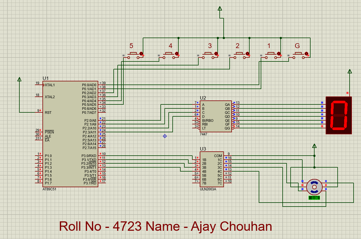
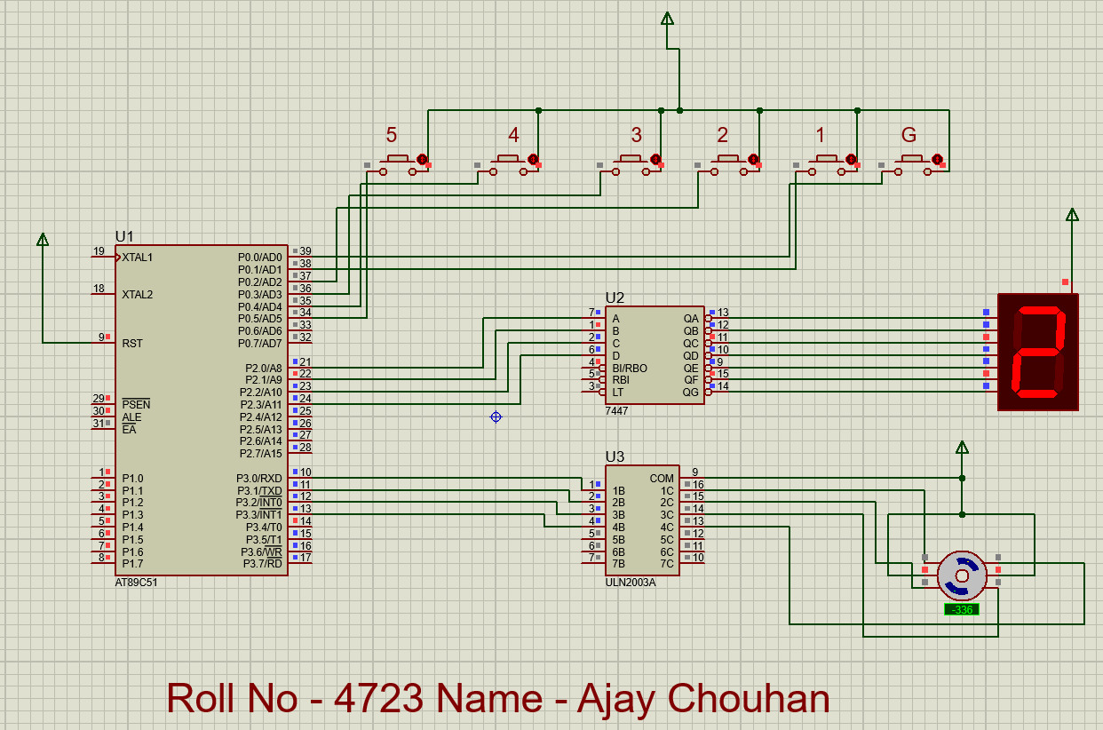
Provides elevator control using the 8051 with a stepper motor. Buttons on Port 0 select floors; the motor moves up/down accordingly; the current floor is displayed on a 7-segment display via a 7447 BCD decoder.